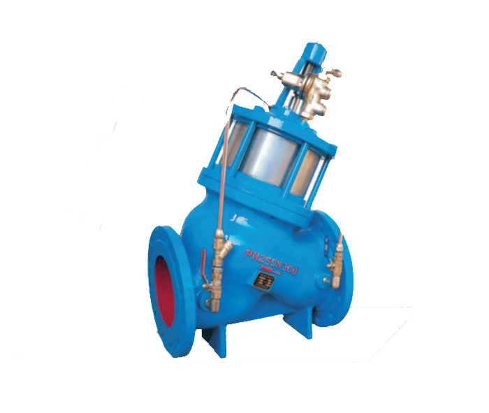
DS104HX Piston Type Pressure Reducing and Regulator Valve
National Advisory Hotline
+86-18752587151Product description
1. Main purpose
It is suitable for reducing pressure from the pipeline, reducing the higher fluctuating pressure upstream to the constant lower pressure required by the user.
2. Features
The decompression range is wide and the application area is wide.
The outlet pressure is stable at the set value and does not change with the upstream pressure.
With hydraulic automatic control system, pressure fluctuation is small.
Full-channel valve body with large flow.
It is convenient to adjust and maintain, and it is reliable.
3. Main technical parameters
Nominal pressure: 1.0Mpa. 1.6 Mpa.2.5 Mpa
Setting pressure: 1.0 Mpa: 0.09-0.9 Mpa
1.6 Mpa: 0.10-1.1 Mpa
2.5 Mpa: 0.15-2.2 Mpa
Applicable medium: water or fluid with physical and chemical properties similar to water.
Medium temperature: 0°C-90°C
Four, structure and working principle
It consists of a main valve and a pilot valve. The main valve and the pilot valve are separated. The pilot valve is the control part. Adjusting the loading force of the pilot valve spring can change the pressure at the outlet end of the main valve to reach the set pressure value, and automatically maintain the outlet by the feedback of the medium's own energy. The pressure is stable at the set value.

Before the pressure reducing and stabilizing valve is operated, the main valve and the pilot valve are closed. When the valve is in use, the medium enters the inlet end and flows under the main valve plate. At the same time, part of the fluid flows through the connecting pipe to the upper part of the control piston and through the guide valve. The valve flows to the outlet end. At this time, the outlet pressure P2 is less than the inlet pressure P1. Due to the medium pressure, the main valve flap moves upward, the valve opens, and the medium flows to the outlet end, and P2 rises accordingly. When the outlet pressure P2 is greater than the pilot valve adjusting spring loading force, the medium will be fed back to the bottom of the pilot valve diaphragm through the connecting pipe C, pushing the pilot valve disc to move in the closing direction, reducing the medium flow area, and making the main valve through the connecting pipe. The pressure Pb of the valve control chamber increases, which makes the main valve diaphragm move downwards, pushes the main valve disc to close, and reduces the medium flowing through the main valve. At this time, the outlet pressure P2 decreases accordingly; on the contrary, if the outlet pressure P2 decreases, the feedback of the medium pressure under the pilot valve diaphragm is less than the loading force of the adjusting spring, which will cause the pilot valve disc to move in the opening direction, and the feedback effect will be The pressure in the control chamber of the main valve is decreased, the main valve flap moves in the opening direction, the medium flow of the main valve is increased, and the outlet pressure P2 rises. It can be seen that by adjusting the pilot valve adjusting screw appropriately, a certain loading force is given to the pilot valve adjusting spring, that is, a required pressure setting value is preset for the valve []. When the pressure at the outlet end of the valve changes, the pilot valve, control chamber and connection will use the feedback of the medium to automatically control the outlet end pressure so that it is basically stable at the set pressure value to ensure the normal operation of the pipeline.
Recommended news
-
What are the common faults of valve special motors
2021-07-22 -
Principles of valve selection in the petroleum and ch…
2021-07-22 -
Application and principle of speed control valve
2021-07-22 -
Types and working principles of gate valves
2021-07-22 -
Do you know everything about the installation of chec…
2021-07-22 -
Why is the use of gate valves forbidden in oxygen pip…
2021-07-22 -
Introduce the working principle of high pressure angl…
2021-07-22 -
Flat gate valve use structure description characteris…
2021-07-22

